MECHANICAL OVERHAUL
of AC's post-war 2 Litre SaloonCooling System

The AC's cooling system is non-pressurised and thus runs at a slighlty lower temperature than a modern system. Typically around 75 deg.C. The original radiator caps were brass with a very fine thread. It takes ages to unscrew! AC modified a lot of ACs to take more modern quick-release caps, but without pressurising the system. There is an over-flow pipe, which is where steam issues if the coolant boils over.

Original brass radiator cap, and its sponge rubber seal.
The alloy passages corrode eventually, depending on how well maintained it is. Coolant tends to stagnate in the rear of the water jacket, causing any debris to be deposited in a fine honey-comb structure. Thus, circulation gets worse and the risk of head-gasket failure increases.
As part of a restoration, it will be a matter of routine to have the radiator re-conditioned with a new core and also remove limescale from the cylinder-head.
The water pump is mounted on the side of the block, and pumps coolant into the engine. This pump can be a source of trouble.
The top radiator hose is very short, and should have a large bulge to permit lateral movement of the engine.

If the cylinder head has been removed for attention, then that is a golden opportunity to clean out all the debris in the water-jacket. Then take measures to avoid further corrosion. Ideally, use purified water, such as reverse osmosis ultra-purified water. If there's no risk of freezing, you can put in some anti-corrosion additive. If you do need antifreeze, keep the percentage down to the minimum required, since water is better at cooling on those hot days. And don't use long-life anti-freeze which can wreck vintage engines. There is some debate over the pros and cons of waterless coolant, and I would avoid it unless some positive data emerges from any experience in AC engines? Using a corrosion resistant coolant can be a problem if the water-pump leaks - as it often does in an AC! See further down the page. One of the worst things for causing corrosion, is draining the coolant out and leaving it without filling straight away. Also, constant topping up with water, if there is leakage, also introduces more dissolved oxygen. Oxygen dissolved in water is largely driven out when it heats up, which is why you don't want fresh water added too often. Reducing corrosion might also improve the working life of the water pump, since its rear plain bearing may deteriorate when debris gets into it.

Thermostat(s)

The engine thermostat is of the bellows type, probably filled with alcohol. It is rated at 78 deg.C. which refers to the temperature at which it is fully open. The valve disc is screwed onto the stem and then soldered to lock it in place. If the solder joint fails, it might unscrew slightly and never fully close. It is easy to repair if this has happened, using a small blow torch, some plumber's solder and some flux paste. Melt off the old solder and clean up the thread and surrounding areas thoroughly (with abrasives). Apply some flux to both threads. Screw the disc on until the valve is closed - but only gently so. Then heat up with the blow-torch until solder will melt into the thread and surrounding area, and quickly remove the heat.

Thermostat with valve disc removed. Note temperature rating.
The thermostat can be tested over a kitchen stove (especially if you are single/divorced!). Strictly speaking, it should be suspended in a pan of water, but I only had a shallow pan. So I rested the unit on the bottom of the pan. Having the thermostat sitting directly against the pan, means that heat conducts through the metal casing causing the thermostat to begin to open early as you heat up the water. It then hesitates to open further, because it conducts less heat when open. It will then continue to open from about 55 deg.C. until fully wide at 78 deg.C.

Important note about engine thermostats: I've heard tales of people fitting lower temperature rated units in an effort to combat over-heating. This practice won't help. It might also do damage over an extended period. A lower temperature thermostat will tend to keep the engine too cool at times. If the cylinder walls fall below a critical temperature, corrosive products of combustion (such as sulphur-trioxide), condense onto the cylinders. This accelerates upper cylinder wear, and the engine will not last as long as it should. The temperature rating of thermostats depends to a large extent on how much pressure the cooling system works with. The AC's is non-pressurised, and uses a 78 deg.C. unit. Pressurised systems on classic cars typically use 82 or 88 degree units, depending on the pressure. I've seen absolute rubbish written by merchants selling thermostats claiming thermal losses affect economy due to changing the coolant temperature. The great Harry Ricardo spent his whole life trying to dispell that fallacy. As our American friends say, "do the math"! Changes in efficiency are due to other factors, not heat loss through cylinder walls.
While the water cooled in the above test, I checked the electric thermostat for the cold-start carb. You need to keep water out of this unit. In fact, the heat has to conduct through the alloy casing from the water passage to the thermo unit. This causes a time delay, which might explain why it's rated so low at 35 deg.C? On mine, 70 deg.C. water took about 30 seconds to trigger the thermo to open. It finally closed again as the water got down to 36 deg.C. The effective time delay, as heat conducts through the casing, no doubt stops it from opening and closing repeatedly. All very clever low-tech stuff!


Electric thermostat for cold starting.
I haven't opened up the electric thermostat, so I don't know how easy it is to repair. For the bellows thermostat, it is probably not worth trying to repair a failed bellows. Either seek out a second-hand replacement, or see if you can convert to a more modern wax thermostat?
The engine thermostat has a locating screw in the side. Unfortunately, this is steel, and its tip is exposed to coolant, where it goes into a slot in the brass part of the unit. Mine broke off (as did the stud extractor I tried!), hence the over-sized hex screw (stainless steel) seen in the photos.
There is a stub pipe on the right of the engine thermostat with a steel adaptor screwed in. This is for the temperature gauge bulb to fit into. The adaptor tends to get encrusted with scale and debris, clogging the small clearance between it and the bulb. So, remember to clear it out so that the bulb will be surrounded by water for a reliable gauge reading.
Water Pump
Note that the minor mods described here have not been tested at the time of writing (July 2021), but are included for your interest.
A problem with the water-pump design, is that the pulley is not bell-shaped as seen on most cars. That means that the fan-belt load is off-set from the ball-race bearing, which in turn, places a side-loading on the plain bearing at the rear of the spindle. Any grit getting into that plain bearing will accelerate its wear. The seal is made from carbon, and is spring-loaded, pressing against a bronze ring. There is an oil-seal behind the ball-race bearing, but this is more useful for keeping water off the bearing. If water leakage is bad, this seal won't last long, and the bearing will fail. There is a cavity between those 2 seals, to catch water leakage and send it down a drain hole. The easiest thing to check is that this drainage hole is clear (it's behind the bottom of the pulley).

Despite the design short-comings, there are some detail issues you can check or improve, with the pump dismantled. The brass rotor has a drive-pin, with its ends hammered over into enlarged holes in the rotor. That is, the pin holes in the rotor, are larger than the hole through the shaft. If the pin is slack fitting, the rotor will be pushed down the shaft (by the spring) and rub against the casing. It also reduces the spring loading of the seal. If the rotor is just 0.5mm out of position (as mine was), the spring load is reduced by about 10%.

Note that the rotor should be as close as possible to the back of the casing, but without touching. It has no back-plate, unlike most other car water-pumps.
I plugged the drive-pin holes in the rotor and re-drilled them at the same 1/8" size as the hole in the shaft. I then fitted a stainless-steel 1/8" split-pin. This makes it easier to remove for future attention. I trimmed the pin to length, taking into consideration the dynamic balance of the pump. That is, having the same weight of pin protruding at each end.
Note the brass drive pin in the photo below. This is for the carbon seal. Check that the seal slides freely over it. It's ends should protrude equally at both ends and the flats should align with the seal.

The next issue is that the spring has nothing to keep it concentric with the shaft. Modern seals have the spring firmly attached to the seal. Someone had added a brass collar inside the spring below, but too small to help. I added a neoprene collar to locate the spring - fitting it just far back enough from the carbon seal, so it doesn't press against it after assembly. Be careful not to restrict the flow of incoming coolant, which goes to the inner ends of the rotor blades.

Even with the spring located, the brass cup washer is too large for the spring, and drops off-centre. If you reverse the cup-washer, it fits perfectly over the neoprene washer. Yet this contradicts the drawing in the AC handbook, and also its installation in the 2 pumps I have.
When I renewed the neoprene washer, I purchased a metric one and trimmed it to imperial size. It is important that it does not distort (such as if it's too tight fitting), otherwise it will interfere with the seal's seating.


The photo below shows the rear casing, with the rear plain bearing installed.

The front end internals laid out, including the old, grotty felt washer.

A new nitrile oil seal inserted from the front end. I bought a type R23 seal, which has an additional lip to keep out contamination. In this case (hopefully), coolant.

After the oil seal and its circlip, the ball-race bearing (and circlip) goes in. I packed it with old style water-pump grease. Then a protective steel washer goes in followed by the felt washer. I cut out a felt washer from wool based felt, soaking it in engine oil first (so it doesn't draw oil out of the bearing). I trimmed its thickness using sheet-metal shears.


With the seal seating evenly (at last!), it is worth checking that the two halves of the casing mate up without a gasket. It might need some fettling for a perfect fit. You can also check if the rotor is touching the casing with or without the gasket, to gauge how precise it is. Then secure the rotor and fit the pulley, which needs a split-pin and either a self-locking nut or a slotted nut and split-pin.

Finally, fit a thin paper gasket, which you can cut out yourself, and apply some suitable sealing compound.

AC stressed the importance of using a very thin paper gasket for the pump to engine block joint. Check that the pump seats correctly against the block and that the flange does in fact mate up.
Note that leakage tends to occur at low revs, or possibly when the engine is switched off. The pump is mounted low down, and the radiator is quite tall, and so there is a head of static pressure. If it leaks when switched off, this might mean the seal is not sitting evenly.
Here are the dimensions of some of the parts for the water-pump:
Ball-race bearing: ID = 1/2" (12.7mm); OD = 1 5/16" (33.34mm); width = 3/8" (9.53mm).
Oil seal: ID = 3/4" (19.05mm); OD = 1 5/16" (33.34mm); width =1/4" (6.35mm).
Neoprene washer: ID = 1/2" (12.7mm); OD = 1 1/8" (28.58mm); thickness = 3/32" (2.4mm).
Carbon seal: ID = 1/2" (12.7mm); OD = 1 1/4" (31.75mm); width = 1/4" (6.35mm); drive-pin notches = 5/32"W x 3/32"H (3.97 x 2.38mm).
Rear bronze bearing: ID = 1/2" (12.7mm); OD = 5/8" (15.88mm); length = 5/8" (15.88mm).
Useful tip: Carry a spare fan-belt that is short enough to drive the fan only. If the water-pump bearing(s) fail, you can fit the short belt, and continue on your journey at reduced speed and topping up coolant if necessary. The radiator is tall enough for thermo-syphon circulation.
The pump cannot be lubricated once it is assembled, unless it has been modified (despite the lubrication charts listing the water-pump).
Fan
With the fan-blades removed, you can dig out the old congealed grease and check the bearings. There's a large self-locking nut holding the assembly together. Otherwise, remove as much old grease as possible, and repack it with fresh grease. The same high temperature grease used on the chassis.
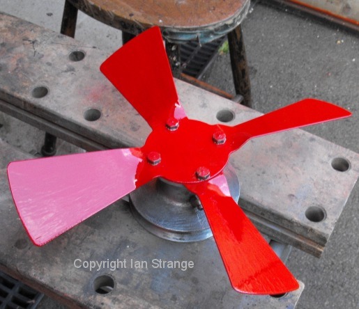
I would recommend painting the blades a bright colour for safety.

Fan-pulley with blades removed, and old grease scooped out.
Electric Fan?
Depending on your local climate, an electric fan might be a useful added extra. This might be automatic or manual, with or without the original mechanical fan.
There's a common mis-understanding about power consumption of a fan. It is usually assumed that power input is proportional to the RPM cubed. But that does not hold true if the fan is in a forward moving car. The faster the car is travelling, the greater the reduction of power input to the fan. That means that removing the mechanical fan, won't make a big improvement in fuel economy.
A dis-advantage of the original fan. is that it is too far away from the radiator to move the air efficiently, and also has a tendency to draw it in near the centre, and fling it out like a radial fan. The more obvious drawback, is that it runs slowly when it is needed the most. That is, the time lag in removing engine heat, means that slowing (or stopping) the car after a fast run, releases a lot of heat when the fan and pump have slowed. The pump is less of an issue on the AC, because it functions well in thermo-syphon 'mode', because the radiator top tank is high up. An electric fan can assist during those "heat soak" moments. It can also help to lower the under bonnet temperature, to cool the intake air, fuel system... and driver's feet! The actual heat-flow will increase at first, as the engine cools, although the air temperature might be lower.
The electric transmission for such a fan is inefficient, but offset by being switched off most of the time. You would need to buy a fan with a fairly low current draw. The AC's generator is rated at 13 amps, and so you want to find a fan that draws far less (continuous rating).
I'm planning to keep the mechanical fan, but also install an electric one to the front of the radiator (hidden and safe), with manual control (and maybe a timer to switch it off?).
Return to the Overhaul Index
